Design verification uses Category, MTTFD, DC, and CCF to verify that the proposed system achieves the required Performance Level. Reliability information on each part of the safety function needs to be collected.
Calculating Number of Operations
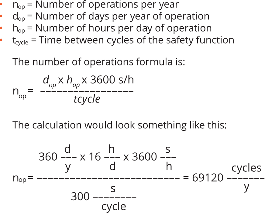
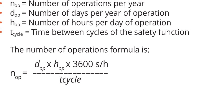
The first step of calculating the MTTFD of a system is determining the Number of Operations (nop) per year of the safety function. This is done by collecting the following information:
Calculating MTTFD
Follow the steps below to calculate the MTTFD and Diagnostic Coverage of your safety system. To view the calculations with a real-world example, visit the page below.
MTTFD Diagnostic Coverage Calculation ExampleThe first step of calculating the MTTFD of a safety system is determining the Number of Operations (nop) per year of the safety function.
This is done by collecting the following information:
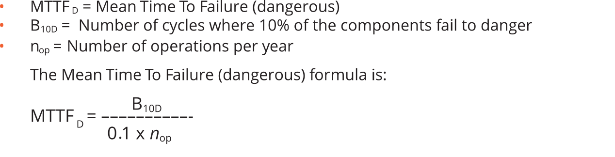
The second step of calculating the MTTFD of a safety system uses the calculated nop and reliability of each component in the safety function to determine the system reliability. Component reliability reporting varies from manufacturer to manufacturer and from device type to device type.
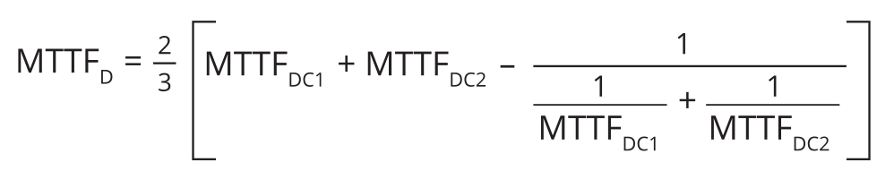
Determine the system’s MTTFD by using the following formula:
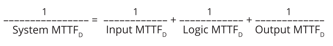
If the input, logic, and output devices are dual-channel devices, or if the same input, logic, and output devices are used on both channels, the calculation is complete. If channel 1 and channel 2 use different devices, an additional symmetrisation calculation must be performed. See example below.
Calculating Diagnostic Coverage (DC)
Follow the steps below to calculate the Diagnostic Coverage of your safety system. To view the calculations with a real-world example, visit the page below.
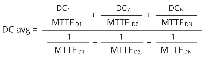
MTTFD Diagnostic Coverage Calculation ExampleDiagnostic Coverage (DC) is a representation of what percentage of faults within the safety system can be detected. DC is calculated by understanding the monitoring potential of each device in the system. Calculating the DC of a system uses the following information (from previous steps):
Determining Common Cause Failures Score
Common Cause Failures (CCF) can be avoided through the use of good engineering practises. The CCF scoring table can be found in table F.1 of ISO 13849-1.
ISO 13849-1 requires the designer to achieve a CCF score of 65 or higher to prove that they have used good engineering and design practises to reduce the effect of systematic failures.
| No. | Measure Against CCF | Maximum Score |
|---|---|---|
| 1 | Separation / Segregation | |
Physical separation between signal paths, for example:
|
15 | |
| 2 | Diversity | |
Different technologies/design or physical principles are used, for example:
|
20 | |
| 3 | Design/application/experience | |
| 3.1 | Protection against over-voltage, over-pressure, over-current, over-temperature, etc. | 15 |
| 3.2 | Components used are well-tried | 5 |
| 4 | Assessment/analysis | |
| For each part for the safety related parts of control system a failure mode and effect analysis has been carried out and its results taken into account to avoid common-cause failures in the design. | 5 | |
| 5 | Competence/training | |
| Training of designers to understand the causes and consequences of common cause failures. | 5 | |
| 6 | Environmental | |
| 6.1 | For electrical/electronic systems, prevention of contamination and electromagnetic disturbances (EMC) to protect against common cause failures in accordance with appropriate standards (e.g. IEC 61326-3-1). Fluidic systems: filtration of the pressure medium, prevention of dirt intake, drainage of compressed air, e.g. in compliance with the component manufacturers’ requirements concerning purity of the pressure medium. NOTE: For combined fluidic and electric systems, both aspects should be considered. | 25 |
| 6.2 | Other influences Consideration of the requirements for immunity to all relevant environmental influences such as, temperature such as, temperature, shock, vibration, humidity (e.g. as specified in relevant standards). | 10 |
| TOTAL | [max. achievable score: 100] |
| Total Score | Measures for avoiding CCFa |
|---|---|
| 65 or better | Meets the requirements |
| Less than 65 | Process failed => choose additional measures |
| *Where technological measures are not relevant, points attached to this column can be considered in the comprehensive calculation. | |
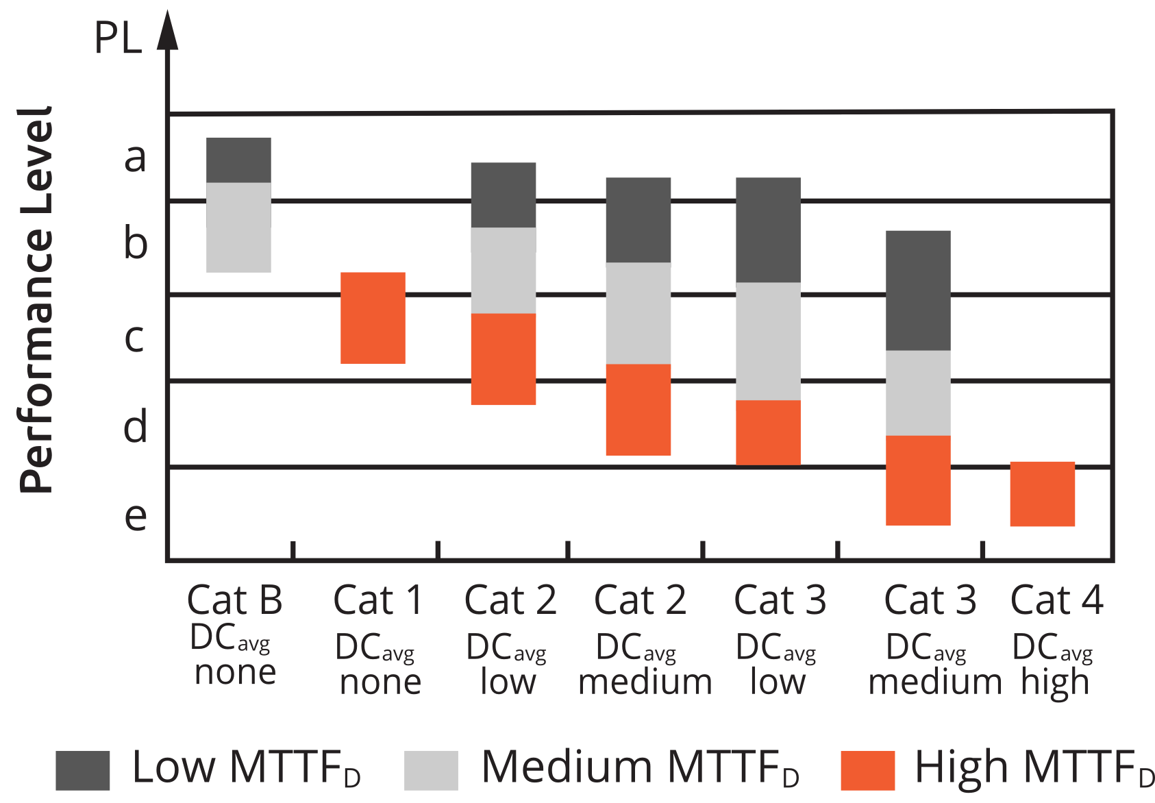
Performance Level
The last step in the design verification process uses the calculated MTTFD, calculated DC, and selected structure to determine if the Performance Level Achieved (PLa) meets or exceeds the Performance Level Required (PLr).
SISTEMA Software
The previous calculations can be cumbersome to perform and difficult to document. The DGUV in Germany publishes the SISTEMA “Safety Integrity Software Tool for the Evaluation of Machine Applications”, which is free software that allows you to create devices and safety functions to verify the PL of the system. The user models the structure based on design architecture and populates the MTTFD or B10D values, DC, and CCF data. Many manufacturers publish SISTEMA data libraries with all pertinent data for their products that can be loaded into the safety function. ROSS’ SISTEMA library can be found on the engineering tools page.
View Engineering Tools