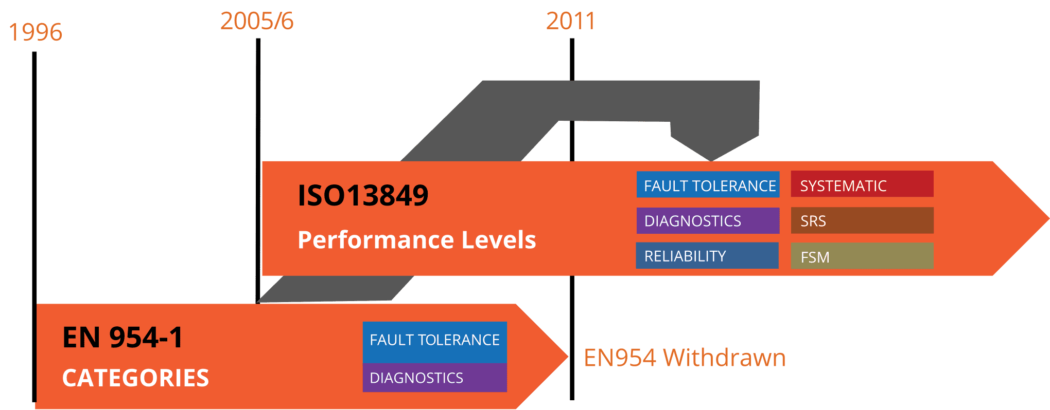
Before diving into the design process, it is important to discuss the control integrity of the safety system. For many years, ANSI standards and OSHA have used the term “control reliable” to define safety system requirements to be used in hazardous applications and for alternative methods of lockout. International standards ISO 13849-1, -2, and IEC 62061, and the Machinery Directive have used terms like “Performance Level (PL)” and “Safety Integrity Level (SIL)” to describe similar concepts and requirements.
Control Reliability
Control reliability is defined in ANSI standards as “The capability of the [machine] control system, the engineering control – devices, other control components, and related interfacing to achieve a safe state in the event of a failure within the safety-related parts of the control system.” In practise, this means that there is not only redundancy in the safety function, but monitoring is included to ensure that the safety function occurs, and that redundancy is maintained.
Applications for control-reliable valves exist anytime reliability is an issue for either hydraulic or pneumatic systems. Typical applications for control-reliable Category 3 or 4 valves include E-stop, two-hand-anti-tie-down, light curtains, safety gates, pneumatic locking devices for safety gates, hydraulic brakes, air brakes, air and hydraulic clutches, rod locks, or any other application where the integrity of the circuit is dependant upon valve operation.
A broad area of applications where control-reliable valves are used is in alternative measures to lockout/tagout (LOTO) for production-related tasks. Currently, non-lockout type valves used to isolate energy for production tasks in the United States must be control-reliable to meet OSHA law.
Safety System Performance According to ISO 13849-1
ISO 13849-1 defines the principles and requirements of safety circuit design and device selection. Part of the device selection process is to obtain detailed specification and functional safety data for possible components that are being considered for use in each safety function to ensure that when the components are integrated into the system, the system will meet or exceed the required Performance Level (PLr).
To design a suitable circuit for a safety function, a category (structure) should be selected as a target and components should be chosen to meet or exceed that target (e.g., Category 3). The reliability data for each component should be evaluated and used to calculate an overall system MTTFD.
Next, a method of monitoring should be chosen, and a system Diagnostic Coverage must be calculated and be sufficient to help achieve the required Performance Level. Measures taken against Common Cause Failures must also be scored with a minimum cumulative score of 65 points.
Once this is all done, the resultant Category, MTTFD, DC, and CCF information can be used to verify that the proposed system achieves the required Performance Level (PLa = PLr). If the achieved Performance Level of the proposed system does not meet or exceed the required Performance Level, a different combination of components with different Categories, MTTFD, DC, and/or CCF will have to be evaluated alternatively. This quite often requires a different selection of components and can be an iterative process that is necessary to develop a system to reduce risk effectively. Examples of how to go through this process of calculations are shown below.
ISO 13849 Benefits
ISO 13849 includes a systematic approach to safety system design and provides quantitative and qualitative analysis factors for reliability and diagnostics. Under this standard, users are required to design safety systems through consideration and implementation of Functional Safety Management (FSM) principles.