Risk assessment is fundamental to machine safeguarding. The goal of a safety system is to reduce risk to an acceptable level with risk being defined as a task & hazard pair. If the risk assessment and the risk reduction are implemented properly, the safety system will be integral to the machine and allow employees safe access to perform their required tasks in a safe, yet unencumbered way. A burdensome safety system is likely to be bypassed or circumvented for expediency and productivity. The risk reduction measure should not create new hazards.
The risk assessment process includes the steps of analysing the inherent risks of the machine, tasks that cause people to be exposed to those inherent risks, and ultimately includes the application of risk reduction methods as well as documenting the results. The whole process should also be considered as an iterative process in which all task & hazard pairs are assessed for severity, frequency, and possibility of avoidance. The risk assessment result would be a category and/or performance level recommendation that risk reduction measures must meet.
If the residual risk is not deemed to be acceptable (tolerable), then the process should be repeated to determine what additional reduction measures need to be applied. However, risk assessment also allows that not all risks can be eliminated or reduced within reasonable economic limits. Whether or not the residual risk is determined to be acceptable is ultimately the responsibility of the end user.
The best approach to performing a risk assessment is as a team, including outsiders, allowing the input of different opinions as to what tasks need to be performed and what hazards exist. ANSI B11.0: 2020 now includes a list of responsibilities for the supplier and user of machinery and recommends points of potential collaboration. The assessment should be expanded beyond human injury to cover damage to the machine and other company assets, as well as damage to the environment. This will result in a safer and more efficient workplace. This does not mean that the manufacturer can eliminate all risk. The manufacturer must identify and communicate any residual risk to the end user.
Risk Estimation Steps According to ISO 12100 and ANSI B11.0
ISO 12100 and ANSI B11.0 provide guidance for the risk assessment process which consists of risk estimation and risk reduction. The flow charts below outline the risk assessment processes for ISO 12100 and ANSI B11.0. While appearing slightly different, the two processes are near identical.
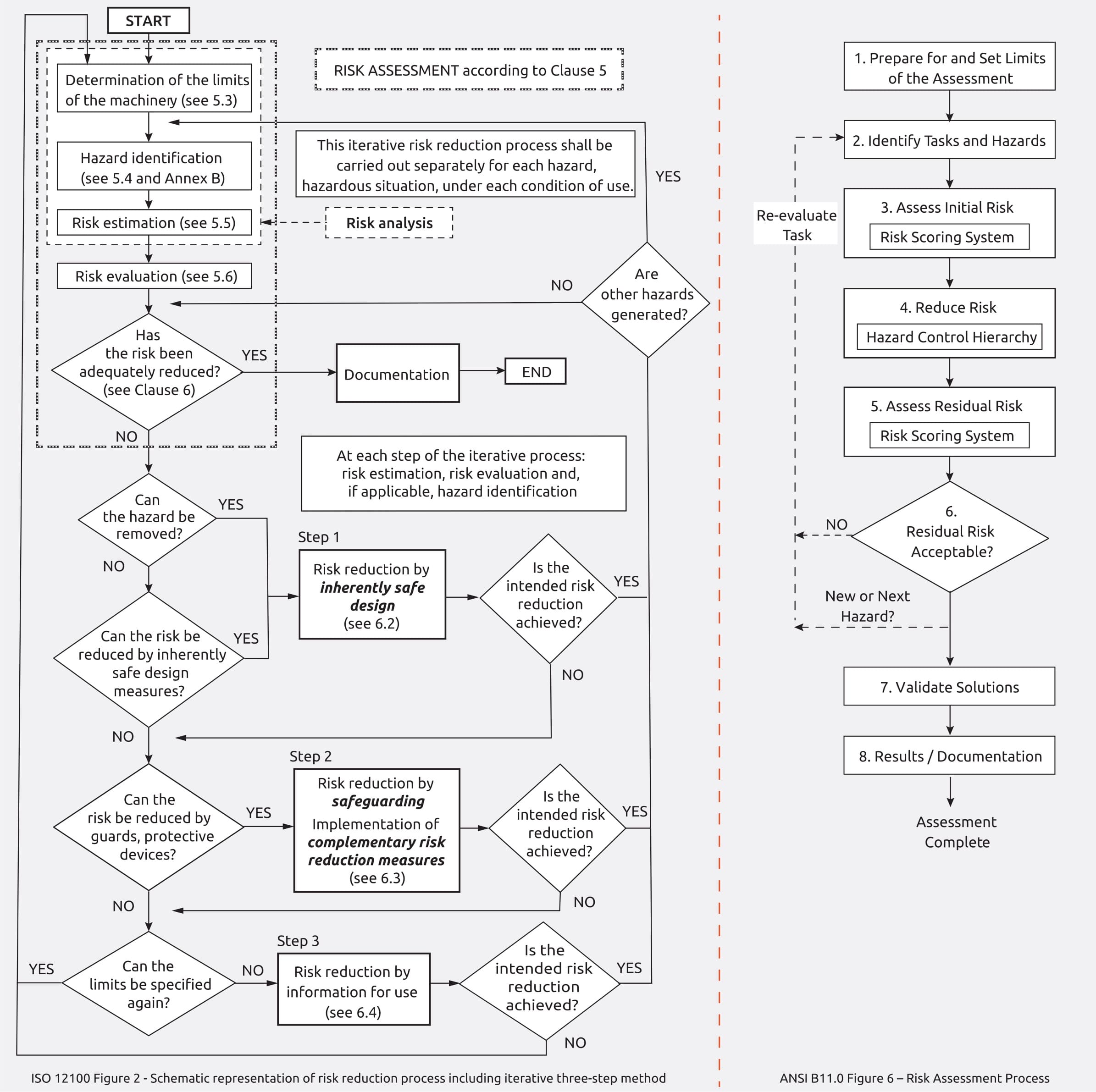
Step 1 is to determine the limits and scope of the machinery and assessment.
Step 2 is to identify tasks and associated hazards. This includes the affected persons, the tasks they perform, and hazards they are exposed to. It is important to not overlook hazards associated with fluid power portions of the safety system.
Step 3 includes initial risk estimation to determine what level of risk reduction is required. There are numerous risk assessment estimation tools available. Selecting one that is best for you is a critical step.
ANSI B11.0 Risk Estimation
The ANSI B11.0 risk estimation matrix shown below uses Severity and Probability to score identified risks. There are four choices each for both severity of harm and probability of occurrence. These are defined in ANSI B11.0 section 6.4.2.
| Probability of Occurrence of Harm | Severity of Harm | |||
|---|---|---|---|---|
| Catastrophic | Serious | Moderate | Minor | |
| Very Likely | High | High | High | Medium |
| Likely | High | High | Medium | Low |
| Unlikely | Medium | Medium | Low | Negligible |
| Remote | Low | Low | Negligible | Negligible |
ISO 13849-1 Risk Estimation
ISO 13849-1 has its own method for determining the performance level required. It has three factors instead of two; severity of injury, frequency of exposure, and possibility to avoid; but only provides two choices for each factor. The risk estimation tool provides a required Performance Level (PLr) a, b, c, d, or e.
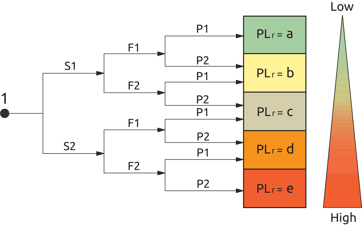 Figure A.1 - Diagram for determining PLr for safety function
H high contribution to risk reduction
PLr required performance level
S1 slight (normally reversible injury)
S2 serious (normally irreversible injury or death)
F frequency and/or exposure times to hazard
F1 seldom-to-less-often and/or exposure time is short
F2 frequent-to-continuous and/or exposure time is long
P possibility of avoiding or limiting harm
P1 possible under specific conditions
P2 scarcely possible
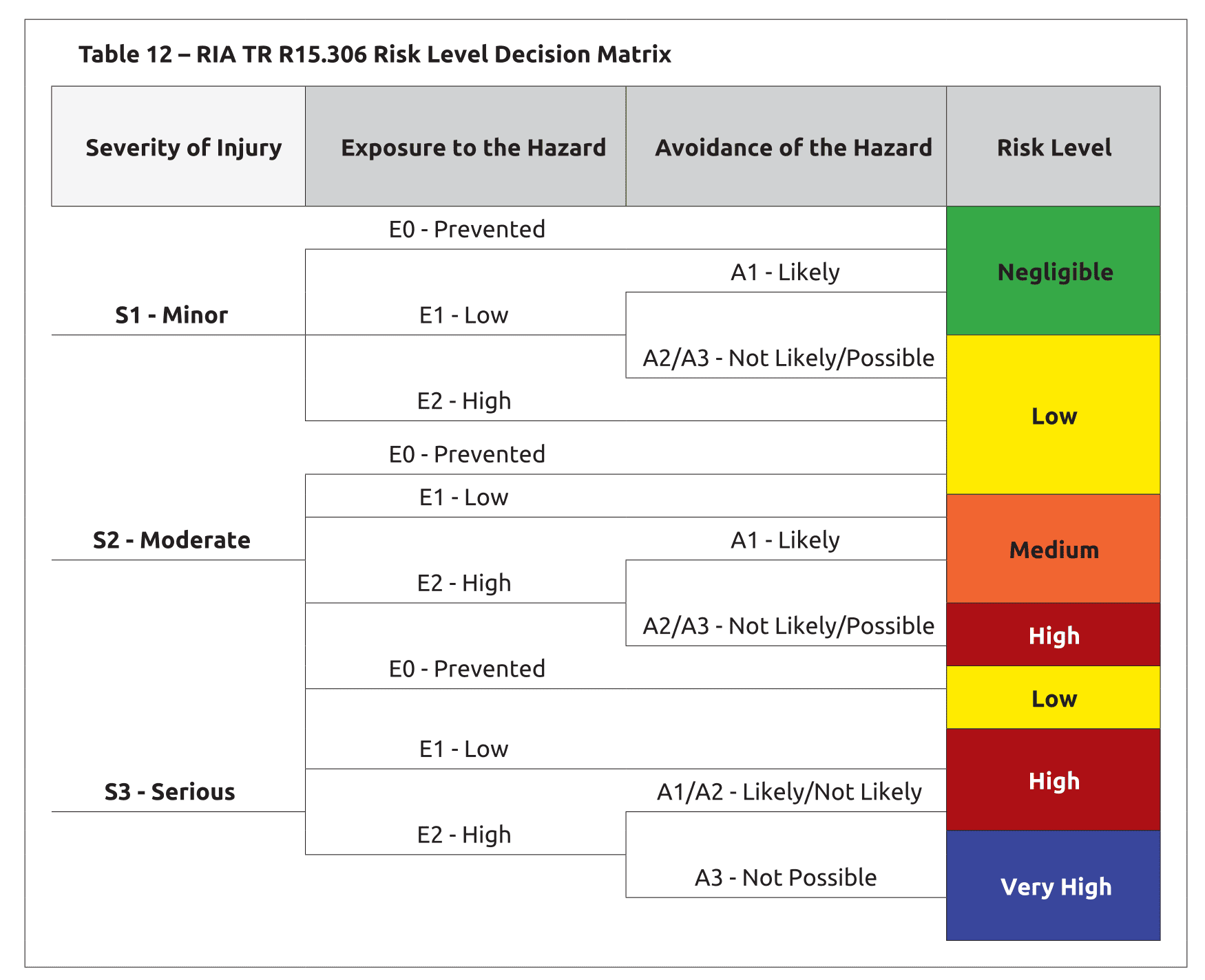
ANSI/RIA TR15.306 Risk Estimation Example
ANSI/RIA TR15.306 uses a hybrid approach that is similar to both the ANSI B11.0 and ISO 13849-1 methods for determining the performance level and category that is required. It has three factors like the ISO 13849-1 methodology, but it results in terms similar to the ANSI B11.0 approach.
An additional table is used to define the performance requirements, much like the ANSI B11.0 methodology.
| Risk Level | Minimum SRP/CS Requirements | |
|---|---|---|
| Pl R | Structure Category | |
| Negligible | c | 1 |
| Low | c | 2 |
| Medium | d | 2 |
| High | d | 3 |
| Very High | e | 4 |
Fluid Power Risk Assessment
Consider:
- Does pneumatic or hydraulic system cause motion?
- Could the pneumatic or hydraulic system cause pinching, shearing, or puncture points?
- Can turning off pneumatic or hydraulic pressure cause things to move?
- Could gravity have an effect?
If there are pinch points, shearing points, and puncture points that are caused by fluid power devices, these hazards must be addressed. Take time to understand the potential failure modes of the valves used in the system; and the severity associated with the hazards based on the pressures and forces being used in the pneumatic or hydraulic system.
Each fluid power actuator (cylinder or otherwise) in the machine’s system must be evaluated as to how it is controlled and what pressures are applied to determine the forces that may be generated. The control scheme of the valves in the system must then be examined to determine both normal and faulted conditions of the fluid power circuit. Lastly, it is important to consider what happens when a safety event occurs and therefore it is crucial to determine what the actuators will do when the valves are de-energised or if a fault occurs.